| Ken'ichi Okamoto |
 |
|
|
 |
 |
|
[Slide 12]
[Slide 13]
[Slide 14]
[Slide 15]
|
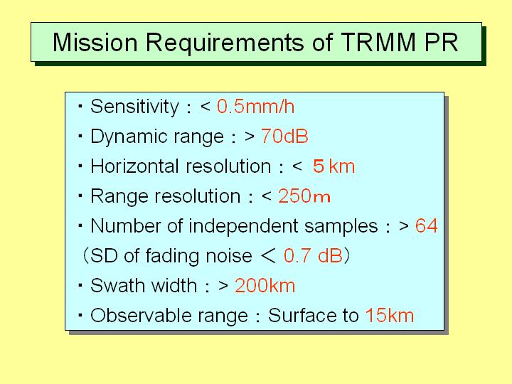
[Slide 12]
Then the TRMM project has started and I was in charge of the system design of the feasibility study. This table shows the user's requirements presented by the scientists of NASA. They wanted to measure the rainfall rate as small as 0.5 mm/h. As for the dynamic range they wanted to measure the sea surface scattering and also weak precipitation, so the dynamic range should be larger than 70 dB. The horizontal resolution should be less than 5 km and the preferred range resolution was less than 250 m. To avoid the fluctuation of noise, the number of independent samples should be more than 64. The preferred swath width was larger than 200 km. The observable range should be as high as 15 km to cover the raining area. These user's requirements were proposed. I tried hard to do the system design to satisfy these requirements.
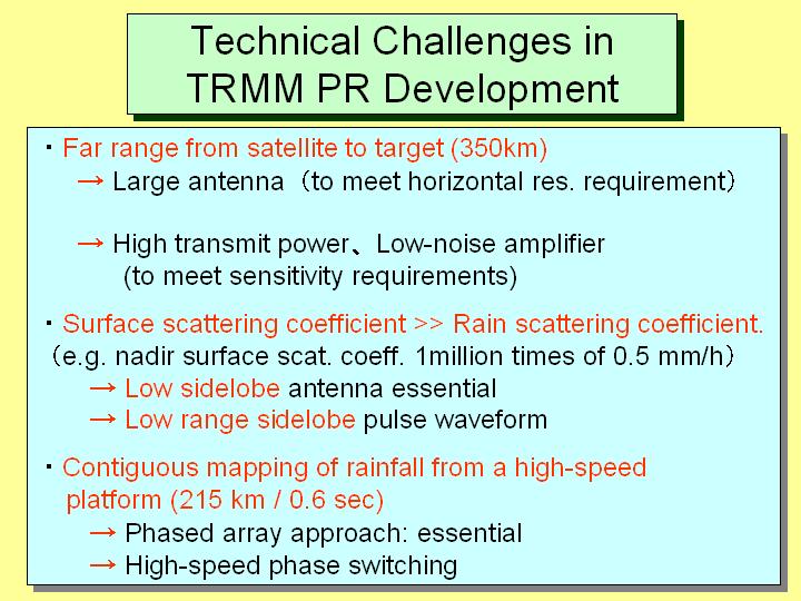
[Slide 13]
This slide shows the technical challenges which we faced. The first point is that the range between the satellite and the target is very large. The range is about 350 km and the horizontal resolution should be less than 5 km. The most important point was the selection of wavelength. The 13.8 GHz and 35 GHz frequencies were allocated to the spaceborne radar. Finally 13.8 GHz was selected. However, this frequency was also attenuated by rain. The resolution of 5 km couldn't be attained without a large antenna. To measure the rain rate of 0.5 mm/h, high transmitter power and a low noise receiver were required. The surface scattering power is overwhelmingly larger than that of rainfall. There is about a 1-million-times difference between the received power from the surface and that from 0.5 mm/h rainfall. Therefore it was essential to reduce the antenna sidelobe level. There was another option of using a pulse compression technique. However, this technique wasn't used in the TRMM precipitation radar. If we adopt this technique, range sidelobe level should be also decreased. The next point is the specific problem for a satellite. It is essential to measure precipitation continuously, i.e. to make a contiguous mapping. The antenna beam should be scanned perpendicularly to the moving direction of a satellite without any gaps between scan lines. As I mentioned before, the horizontal resolution is limited by the footprint size of 5 km. While a satellite moves at a distance of 5 km, the width of 215 km should be scanned. The speed of a satellite is about 7 km/sec. Therefore within the time of about 0.6 sec, the width of 215 km should be scanned. To achieve this, it is very difficult to rotate an antenna mechanically. If such a large antenna is rotated on a satellite, the attitude of a satellite will be seriously affected. There was no other way of scanning the antenna beam but electrical scanning, so we chose the high-speed phased array method. The last problem was very difficult to solve by using the instruments that were used for the airplane experiment.
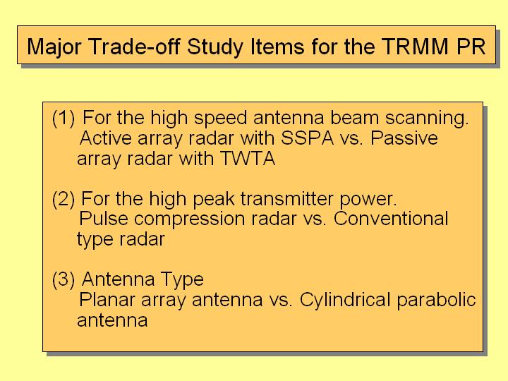
[Slide 14]
Actually we had many difficult issues, but three major trade-off items are shown in this slide. For the high speed antenna beam scanning, a high-speed phased array was used. As for the phased array type, there are two types. One is the passive array and the other is the active array. In passive array, very large transmitter power TWTA should be used. The other is an active array with a solid state power amplifier. I will explain this in detail in the next slide. The next issue is to select either the pulse compression type radar or the conventional type radar. The aim of this selection is to get a high peak transmitter power. As for the antenna type, there were studies to select either a planar array antenna (slotted wave-guide antenna) or a cylindrical parabolic antenna. We studied hard mainly these three trade-off items.
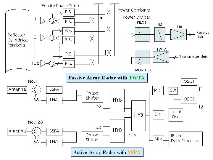
[Slide 15]
The first issue was whether we should select a passive array or an active array. In passive array radar, high power TWTA is used. This is a very high power transmitter unit and the power is divided and fed to antennas. The received power by antenna is combined and then amplified by a LNA. The composition is very simple and light weight. This is a merit of this type of radar. However, if TWTA or LNA do not function, the whole system will die. This is a disadvantage of this type of radar. In active array radar, there are many devices. In the case of TRMM, 128 units are used. In addition to antenna units, solid state power amplifiers (SSPA), low noise amplifiers and so on are equipped. Briefly speaking, each unit is small radar and the output power is small. However, by combining these small powers together, large powers can be obtained. This system is composed of many small radars, so even if one unit does not function, the total system suffers almost no damage. Since the power to SSPA is small, we don't worry about power supply. It is very difficult to fabricate an electric power supply for a high-power pulse TWTA. On the contrary, it is rather easy to make an electric power supply for solid devices. Japan was familiar with making solid devices, so this radar could be developed with only Japanese devices and techniques. So we decided to adopt the active array radar. Although the heavy weight and the complicated system, the fail-safe capability was the key points in selecting this type of radar. Five years have passed since TRMM was launched and the mission life of 3 years has passed. Fortunately not even one device has malfunctioned. Probably, as many devices were damaged by the experiments done on the ground, so everything has gone well on the satellite. I'm glad it is not the other way round.
|
|
|